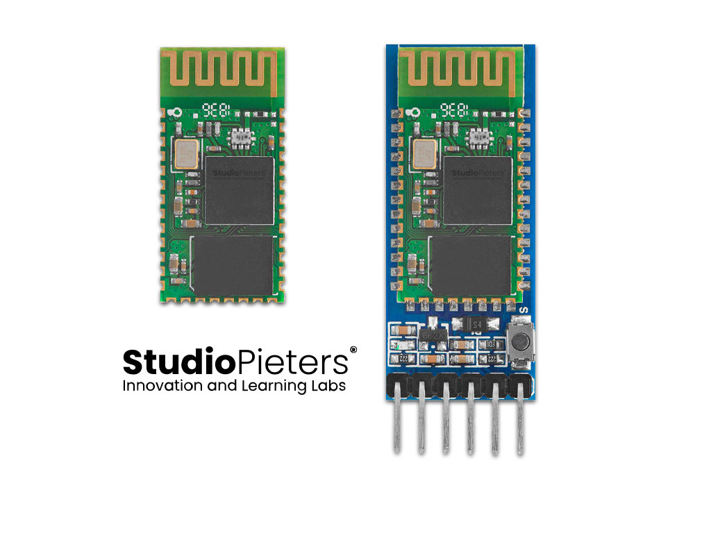
The HC-05 Bluetooth module is a popular choice for integrating wireless communication into microcontroller projects. It supports both master and slave modes, making it versatile for various tasks, such as connecting an Arduino to smartphones, laptops, or other Bluetooth-enabled devices. In this post, we’ll explore the HC-05 bare module and the HC-05 breakout (Arduino) module and their pinout, understanding the differences and uses of both.

HC-05 Bare Module Pinout
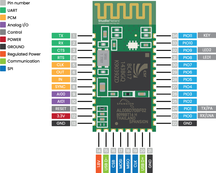
The bare HC-05 module is typically used when integrating Bluetooth communication into custom PCBs or when size constraints are critical. It has 34 pins that allow for flexible integration, though it requires some knowledge of its internals.

Pin Functions:
- UART Pins (TX, RX, CTS, RTS): These handle the UART communication with microcontrollers like Arduino. For example, the
TXpin transmits data from the module, while theRXpin receives data. - PCM Pins (PCM_CLK, PCM_OUT, PCM_IN, PCM_SYNC): These pins are typically used for audio-related applications.
- AIO0, AIO1: General-purpose analogue I/O pins.
- PIO Pins (PIO0-11): Programmable I/O pins that can be used for various control tasks. For example,
PIO8andPIO9are commonly connected to status LEDs. - RESET: Used to reset the module.
- USB Pins (USB_D+, USB_D-): For connecting to USB interfaces.
- VCC & GND: Power (3.3V) and ground.
The KEY pin (PIO11) is used to toggle between data mode and AT command mode, which is essential for configuring the module settings like baud rate or name.

The pinout and functions of the HC-05 Bluetooth module based on your provided image and data from the datasheet are as follows:
| Pin Number | Pin Name | Function Description | Special Notes |
|---|---|---|---|
| 1 | UART_TX | UART Data Output | Transmit data |
| 2 | UART_RX | UART Data Input | Receive data |
| 3 | UART_CTS | UART Clear to Send (active low) | Flow control input |
| 4 | UART_RTS | UART Request to Send (active low) | Flow control output |
| 5 | PCM_CLK | Pulse Code Modulation Clock | Bidirectional PCM clock |
| 6 | PCM_OUT | PCM Data Output | |
| 7 | PCM_IN | PCM Data Input | |
| 8 | PCM_SYNC | PCM Sync Signal | |
| 9 | AIO0 | Programmable Analog I/O | |
| 10 | AIO1 | Programmable Analog I/O | |
| 11 | RESET | Reset Input (active low) | Resets the module |
| 12 | VCC | Power Supply (3.3V) | |
| 13 | GND | Ground | |
| 14 | 1V8 | Integrated 1.8V Regulator Output | |
| 15 | USB_D- | USB Data – | |
| 16 | SPI_CSB | SPI Chip Select (active low) | Selects the SPI bus |
| 17 | SPI_MOSI | SPI Data Input | Master Out Slave In |
| 18 | SPI_MISO | SPI Data Output | Master In Slave Out |
| 19 | SPI_CLK | SPI Clock Input | |
| 20 | USB_D+ | USB Data + | |
| 21 | GND | Ground | |
| 22 | GND | Ground | |
| 23 | PIO0 | Programmable I/O | RX Enable for LNA |
| 24 | PIO1 | Programmable I/O | TX Enable for PA |
| 25 | PIO2 | Programmable I/O | |
| 26 | PIO3 | Programmable I/O | |
| 27 | PIO4 | Programmable I/O | |
| 28 | PIO5 | Programmable I/O | |
| 29 | PIO6 | Programmable I/O | |
| 30 | PIO7 | Programmable I/O | |
| 31 | PIO8 | Programmable I/O | Controls LED1 |
| 32 | PIO9 | Programmable I/O | Controls LED2 |
| 33 | PIO10 | Programmable I/O | |
| 34 | PIO11 | Programmable I/O (KEY) | Activates AT Command Mode |
HC-05 Breakout Module (Arduino Module) Pinout
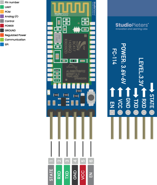
The breakout board simplifies the use of the HC-05 module, as it is designed for easy integration with development boards like the Arduino. It contains fewer accessible pins, but the most essential ones are exposed for quick setup. The breakout module typically has six to eight pins, making it less intimidating for beginners.

Common Pinouts for the Breakout Module:
- VCC: Connects to 5V or 3.3V power (depending on the breakout board design).
- GND: Ground connection.
- TXD (Transmit): Sends data to the RX pin of a microcontroller.
- RXD (Receive): Receives data from the TX pin of a microcontroller. Often, a voltage divider or level shifter is required if connecting to a 5V microcontroller.
- STATE: This pin indicates whether the module is connected to another Bluetooth device. It outputs a HIGH signal when connected and LOW when not connected.
- EN or KEY: This pin enables AT command mode, allowing you to configure the module. Hold it HIGH when powering the module to access AT mode.

Differences Between the Bare and Breakout Module
- Accessibility: The bare module offers more control and flexibility but requires a deeper understanding of the hardware. The breakout module simplifies the setup process and is designed for quick prototyping with platforms like Arduino.
- Pin Count: The bare module has 34 pins, providing full access to all the module’s features. The breakout module offers fewer pins, focusing only on the essential ones for basic Bluetooth communication.
- Voltage: The bare module operates at 3.3V, while many breakout boards come with a voltage regulator to handle 5V, making them more compatible with standard Arduino boards.
- AT Command Mode: Both versions can be programmed with AT commands to configure parameters like the baud rate, role (master or slave), and device name. The KEY pin (or a button on some breakout boards) toggles the module between data and AT modes.
Typical Applications
- Bare HC-05 Module: Ideal for custom PCB designs where space and access to multiple pins are crucial. It’s often used in complex projects requiring programmable I/O pins or specific functionalities like audio.
- Breakout Module: Popular for rapid prototyping with platforms like Arduino. It’s perfect for DIY projects where ease of use and quick Bluetooth communication setups are needed.
Conclusion
Whether you’re using the bare module for intricate designs or the breakout version for quick Arduino projects, the HC-05 Bluetooth module is a reliable solution for wireless communication. With its support for both master and slave modes, it’s flexible enough to fit a wide range of applications.
