
Guide
Arduino Nano Pinout
The complete pin reference for the classic ATmega328P-based Arduino Nano: 14 digital pins, 8 analog inputs, and the exact pins you can safely reuse.
Overview
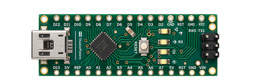
This guide covers the classic Arduino Nano: a breadboard-friendly board built around the ATmega328P, the same chip as the Arduino Uno, just on a smaller DIP-style footprint. No Wi-Fi, no Bluetooth, this is a plain 5V AVR board, which is exactly why it’s still a common choice for simple, no-nonsense projects.
Getting started
The Nano ships with three different USB connectors depending on the revision and clone: original Mini-USB, most common Micro-USB, or newer USB-C boards. Check which one your board actually has before assuming you’re missing a cable.
Hello World: blink an LED
The microcontroller equivalent of “Hello World”: the onboard “L” LED on D13 toggles once a second. No wiring needed, this LED is already built into the board. There’s no ESP-IDF equivalent here, the Nano only speaks Arduino’s AVR toolchain.
#define LED_PIN 13 // onboard "L" LED
void setup() {
  pinMode(LED_PIN, OUTPUT);
}

void loop() {
  digitalWrite(LED_PIN, HIGH);
  delay(1000);
  digitalWrite(LED_PIN, LOW);
  delay(1000);
}
Select Tools → Board → Arduino Nano first, see “Getting started” above.
Specifications
Official specifications for the ATmega328P-based Arduino Nano.
Compute
| Chip | ATmega328P |
| CPU | 8-bit AVR, 16 MHz |
| SRAM | 2 KB |
| Flash | 32 KB (0.5 KB used by the bootloader) |
| EEPROM | 1 KB |
Power
| Logic level | 5V |
| Recommended input (VIN) | 7V – 12V |
| Max current per pin | 40 mA (20 mA recommended) |
| Max current, all pins | 200 mA |
Physical
| Digital I/O pins | 14 (6 with PWM) |
| Analog input pins | 8 (A6/A7 input-only) |
| Dimensions | 45 × 18 mm |

Pinout diagram
Every pin on the Arduino Nano, including the underlying ATmega328P port names (PB/PC/PD) alongside the Arduino digital/analog numbering.

GPIO quick reference
A4/A5 are the default I2C pins, D11–D13 the default SPI pins, both shared with the analog/digital pins listed below.
| Pin | AVR port | Special function | PWM | Notes |
|---|---|---|---|---|
| D0 | PD0 | UART RXD | No | Free |
| D1 | PD1 | UART TXD | No | Free |
| D2 | PD2 | External interrupt 0 (INT0) | No | Free |
| D3 | PD3 | External interrupt 1 (INT1) | Yes | Free |
| D4 | PD4 | — | No | Free |
| D5 | PD5 | — | Yes | Free |
| D6 | PD6 | — | Yes | Free |
| D7 | PD7 | — | No | Free |
| D8 | PB0 | Input capture (ICP1) | No | Free |
| D9 | PB1 | — | Yes | Free |
| D10 | PB2 | SPI SS | Yes | Free |
| D11 | PB3 | SPI MOSI | Yes | Free |
| D12 | PB4 | SPI MISO | No | Free |
| D13 | PB5 | SPI SCK, onboard “L” LED | No | Free |
| A0 | PC0 | Analog input (ADC0) | No | Free |
| A1 | PC1 | Analog input (ADC1) | No | Free |
| A2 | PC2 | Analog input (ADC2) | No | Free |
| A3 | PC3 | Analog input (ADC3) | No | Free |
| A4 | PC4 | Analog input (ADC4), I2C SDA | No | Free |
| A5 | PC5 | Analog input (ADC5), I2C SCL | No | Free |
| A6 | — | Analog input only (ADC6), no digital use | No | Input only |
| A7 | — | Analog input only (ADC7), no digital use | No | Input only |
Programming (USB)
Unlike the ESP32 boards in these guides, the Nano has no manual boot-mode pin to hold. An onboard USB-to-serial chip toggles RESET automatically (via the DTR line) when you click Upload, that’s also why D0/D1 briefly glitch at power-up, they’re shared with that same USB-serial link.
| Function | Pin | Description |
|---|---|---|
| TXD | D1 | Nano → PC (output) |
| RXD | D0 | PC → Nano (input) |
| RESET | RST | Toggled automatically by the USB-serial chip on upload |
Safety notes
Before you wire anything up
- This is a 5V board, not 3.3V tolerant, don’t connect a 3.3V-only sensor’s output directly without a level shifter.
- Don’t exceed 40mA per pin (20mA recommended) or 200mA total across all pins combined.
- A6 and A7 are analog input only, they can’t be used as digital I/O like the other analog pins.
- D0 and D1 are shared with the USB-serial link, avoid using them for anything else while the board stays connected to USB.
Related
 Reference
PCA9685 16-Channel PWM/Servo Driver
A 16-channel, 12-bit I2C PWM driver that turns two ESP32 wires into enough hardware-generated outputs for a whole rack of servos or an LED array. Covers the pinout, address selection, register map, and the safe way to power servos without browning out the board.
Read more
Guide
ESP32-C61 Pinout
The complete pin reference for the ESP32-C61: Espressif’s budget Wi-Fi 6 chip, and the exact pins you can safely reuse.
Read more
Reference
PCA9685 16-Channel PWM/Servo Driver
A 16-channel, 12-bit I2C PWM driver that turns two ESP32 wires into enough hardware-generated outputs for a whole rack of servos or an LED array. Covers the pinout, address selection, register map, and the safe way to power servos without browning out the board.
Read more
Guide
ESP32-C61 Pinout
The complete pin reference for the ESP32-C61: Espressif’s budget Wi-Fi 6 chip, and the exact pins you can safely reuse.
Read more
 Guide
ESP32-S2 Mini Pinout
The complete pin reference for the WEMOS/Lolin S2 Mini: native USB, 14 capacitive touch pins, and no Bluetooth at all.
Read more
Guide
ESP32-S2 Mini Pinout
The complete pin reference for the WEMOS/Lolin S2 Mini: native USB, 14 capacitive touch pins, and no Bluetooth at all.
Read more
More guides
Keep building.
From ESP32 HomeKit accessories to Arduino and ATtiny reference guides, there’s more where this came from.
All guides