Welcome to the world of smart home innovation! If you’re eager to enhance your living space with cutting-edge technology, you’ve come to the right place. Today, we’ll show you how to transform the versatile ESP32 microcontroller into a HomeKit-enabled switch, complete with a responsive push button. Imagine controlling your lights, appliances, and more—all with a simple tap on your iPhone or a quick command to Siri. This step-by-step guide is designed for enthusiasts of all levels, walking you through the entire process from wiring the hardware to integrating it seamlessly with Apple’s HomeKit ecosystem. Whether you’re a DIY veteran or just starting out, this project will empower you to take your home automation to the next level. So, let’s get started and make your smart home dreams a reality!

Setting up the Development Environment
Before you can compile the code, you need to install all the prerequisites that are needed. I have written a separate blog that explains step-by-step how to set up the development environment.
Hardware
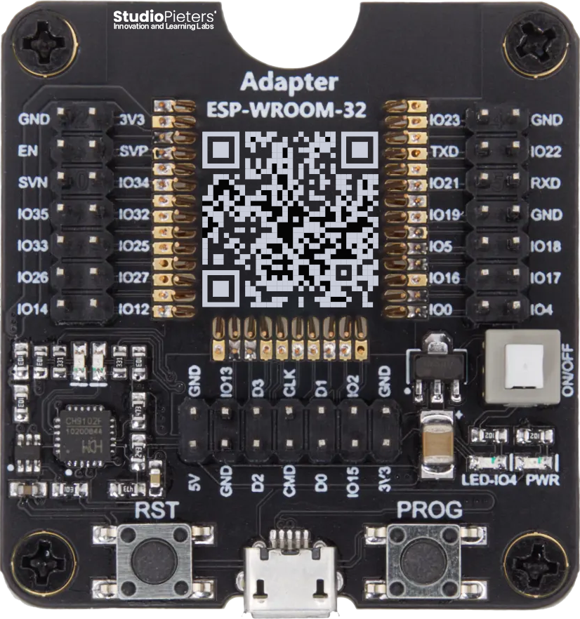
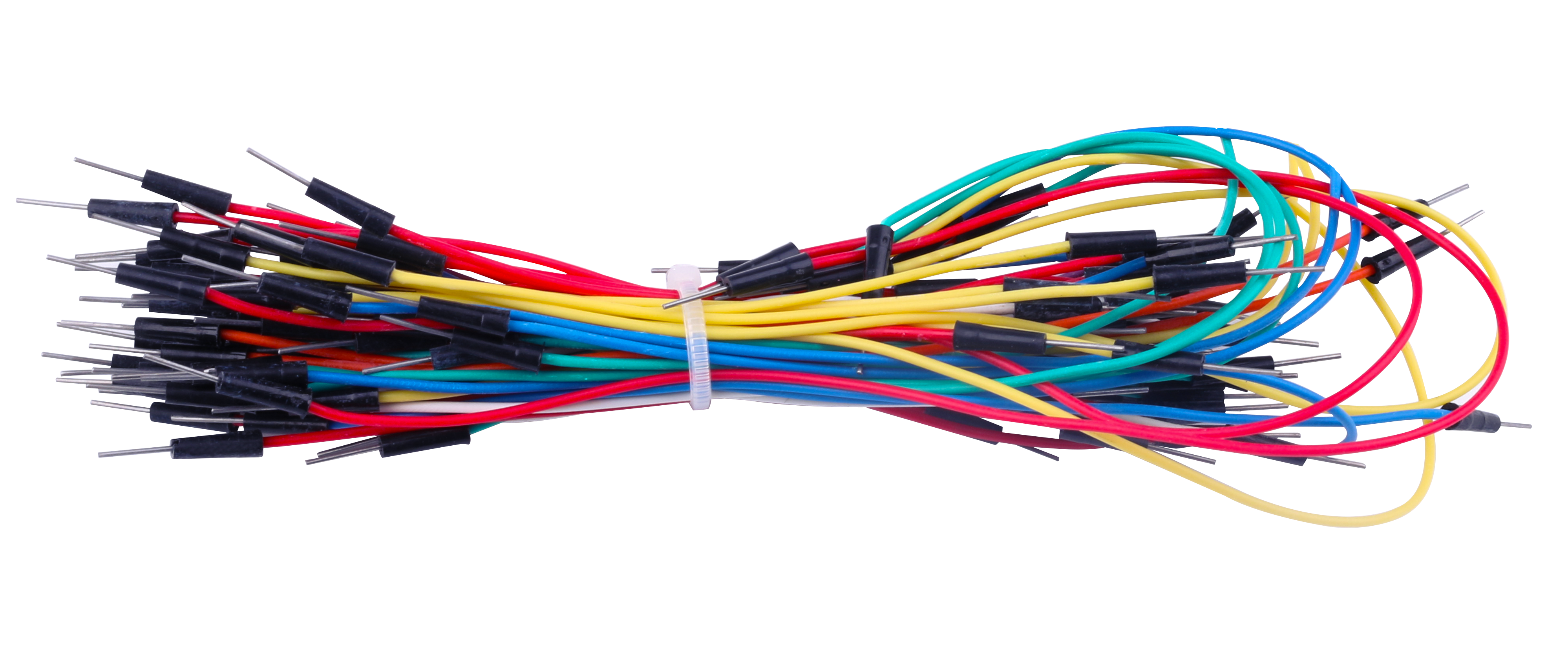
To demonstrate each setup, I use the ESP32 microcontroller. This microcontroller is perfect for both beginners and advanced users. It is easy to use because all IO pins are accessible via headers. The module features TX/RX and power LEDs, as well as reset and boot buttons. Additionally, you’ll need some Dupont cables (Male / Female) and a push button.
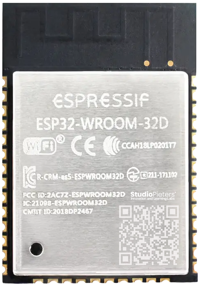
The ESP32-WROOM-32D is a powerful, generic Wi-Fi + Bluetooth® + Bluetooth LE MCU modules that target a wide variety of applications, ranging from low-power sensor networks to the most demanding tasks. More information about this Module can be found here.
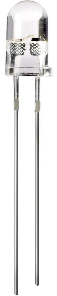
Additionally, you’ll need some Dupont cables (Male / Female), an LED, a push button and a Relay.

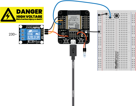
Scheme
We place the ESP32 on the programmer. Connect the LED to GPIO2, the push button to GPIO33 and the relay to GPIO34 using Dupont wires. Then connect the programmer with a USB to Micro USB cable from your computer. Push the ON/OFF button; the power LED (red) on the programmer should turn on.
Push Button and Relay
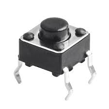
Mini Push button Switch
The mini push button switch is an essential component for creating user interfaces on microcontroller projects. It has four pins: two pins for the switch contacts and two pins for mounting stability. The push button operates by connecting or disconnecting the two switch contact pins when pressed.
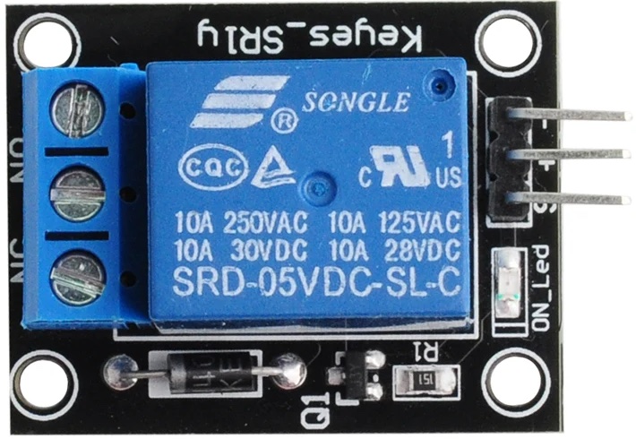
The relay has 3 pins: Two pins for power VCC and GND, the third pin is for the signal, turning it on or off.

Cloning the Repository
First things first, we need to clone the repository containing the necessary files for our HomeKit demo. Open your terminal and execute the following command:
git clone --recursive https://github.com/AchimPieters/esp32-homekit-demo.git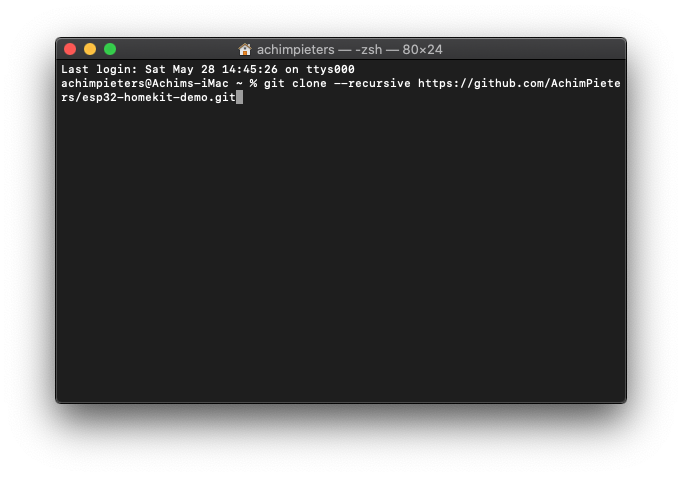
This will download all the required files onto your system.
Docker
Now, let’s set up our development environment using Docker. Run the following command:
docker run -it -v ~/esp32-homekit-demo:/project -w /project espressif/idf:release-v5.3This command will create a Docker container with the ESP-IDF environment, allowing us to compile and flash our code seamlessly.
Configuration
Navigate to the programmable switch example directory:
cd examples/switchSet the target for the ESP32:
idf.py set-target esp32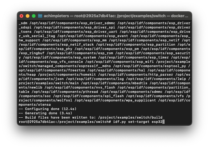
Now, configure the project:
idf.py menuconfig
In the menuconfig, make the following selections: Choose “StudioPieters” and fill in your Wi-Fi network name under “(mysid)” Wi-Fi SSID, and your Wi-Fi network password under “(mypassword)” Wi-Fi Password.
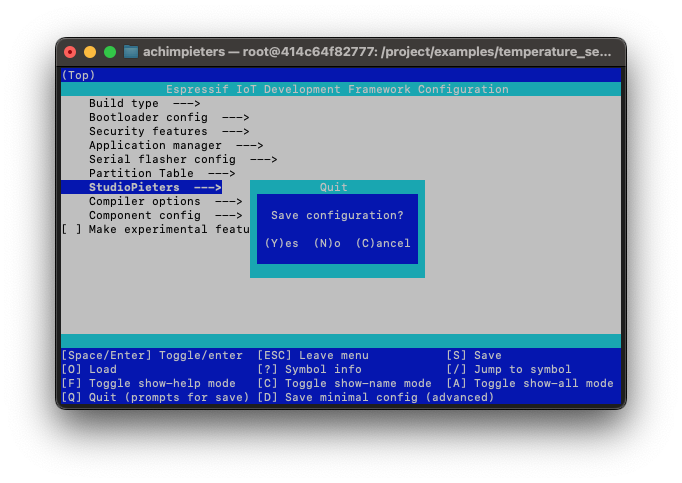
Press ESC until you’re prompted to save the configuration, then select Yes.
Building and Flashing
Build the project:
idf.py build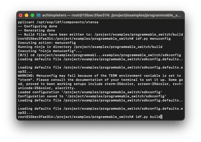
Wait until the code is compiled, this can take some time depending on your computer hardware. Open a new terminal window on your Mac and navigate to the programmable switch example directory:
cd esp32-homekit-demo/examples/switch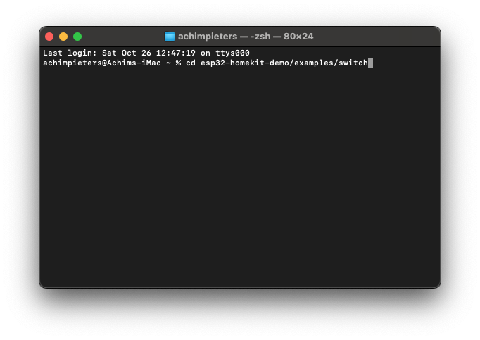
Connect the ESP32 to your computer. Erase the flash memory of your ESP32:
esptool.py erase_flashNow, flash the compiled code onto your ESP32. Replace /dev/tty.usbserial-01FD1166 with your USB port:
python -m esptool --chip esp32 -b 460800 --before default_reset --after hard_reset write_flash --flash_mode dio --flash_size 4MB --flash_freq 40m 0x1000 build/bootloader/bootloader.bin 0x8000 build/partition_table/partition-table.bin 0x10000 build/main.bin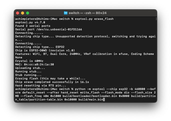
Connecting to Serial Output
Lastly, to view the serial output of your ESP32, run the following command in a new terminal window. Again, replace /dev/tty.usbserial-01FD1166 with your USB port:
screen /dev/tty.usbserial-01FD1166 115200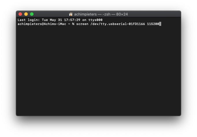
Connecting Your ESP32 to HomeKit
Congratulations on reaching this exciting stage of your HomeKit development journey! Now, it’s time to test whether everything works seamlessly. Follow these steps to connect your ESP32 device to HomeKit:
Open Your HomeKit App: Launch your HomeKit app on your smartphone or tablet.
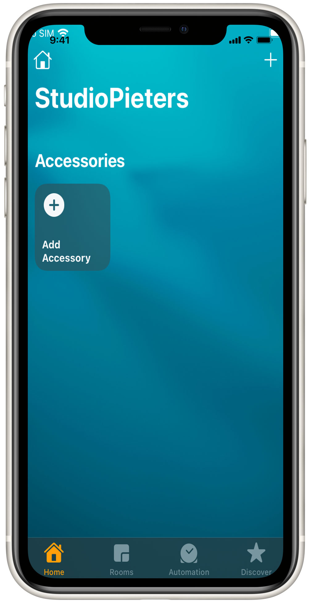
Scan the QR Code: Find the QR code provided below and scan it using your HomeKit app. This will initiate the process of adding your device to your HomeKit network.
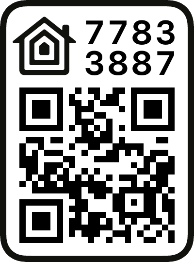
Add Your Device: After scanning the QR code, HomeKit will detect your device as a programmable switch. Press “Add to Home” to begin the integration process.
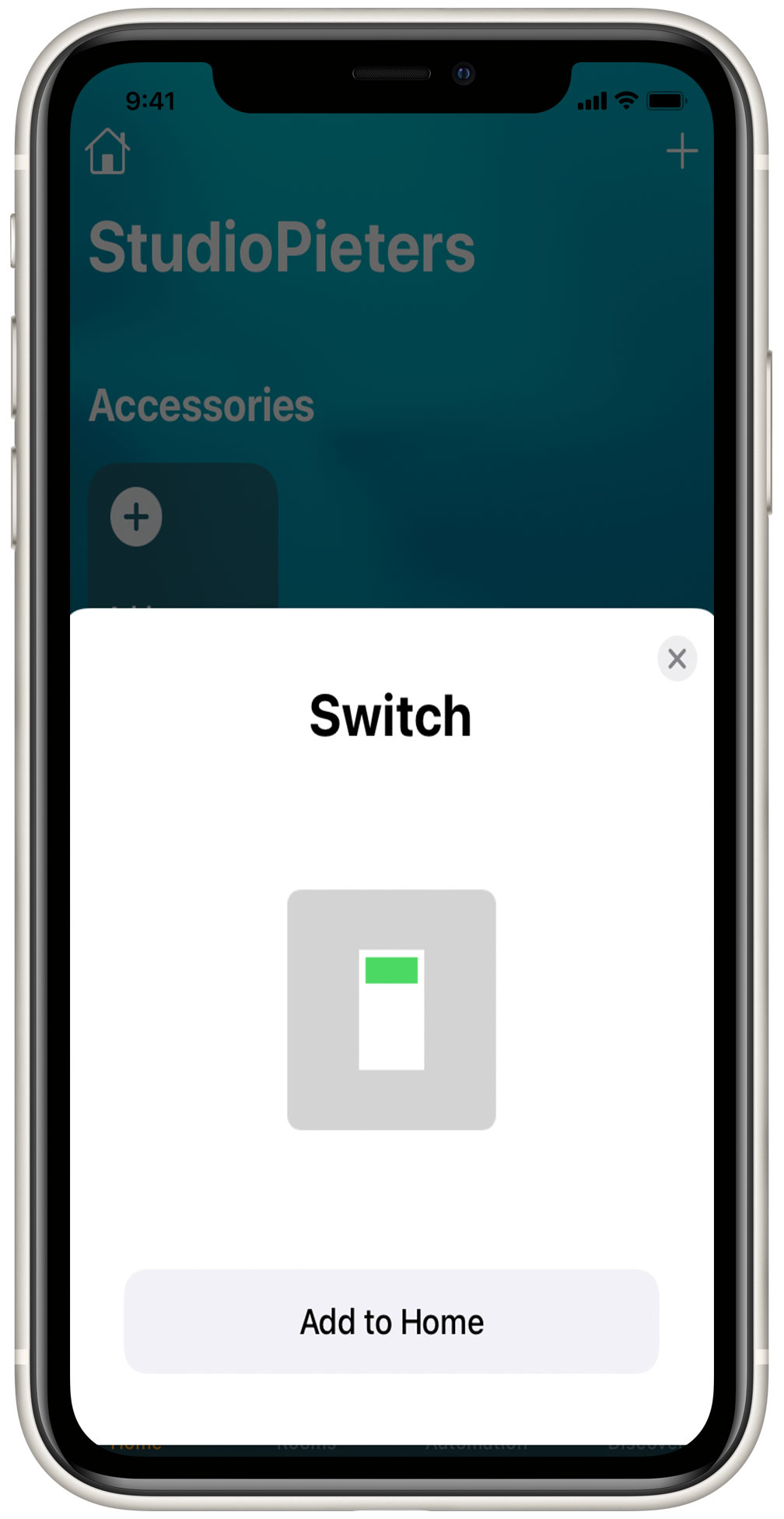
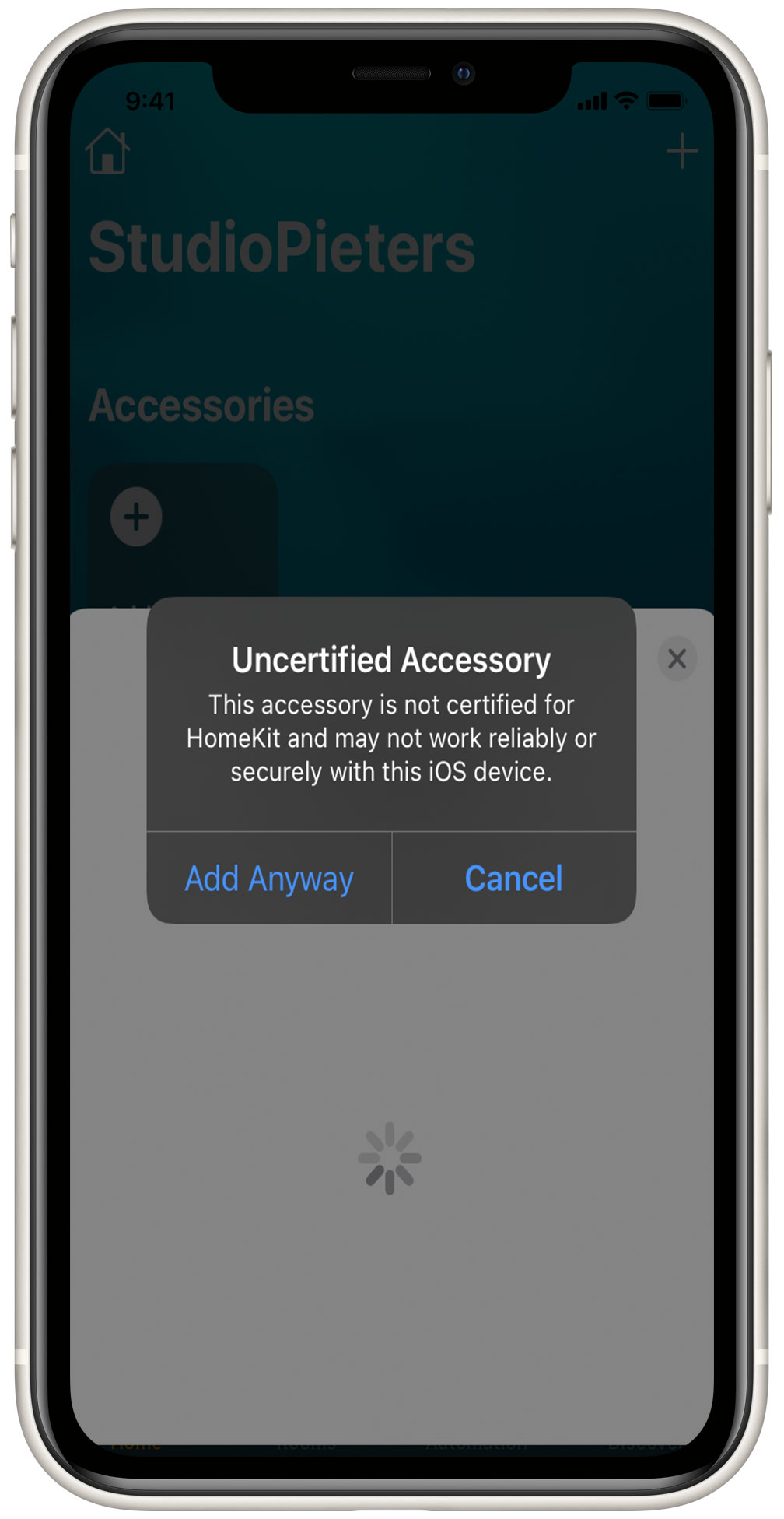
Acknowledge the Uncertified Accessory Prompt: HomeKit may display a prompt indicating that the accessory is uncertified. Don’t worry – this is normal for DIY projects. Simply click “Add Anyway” to proceed with adding your device to your HomeKit network.
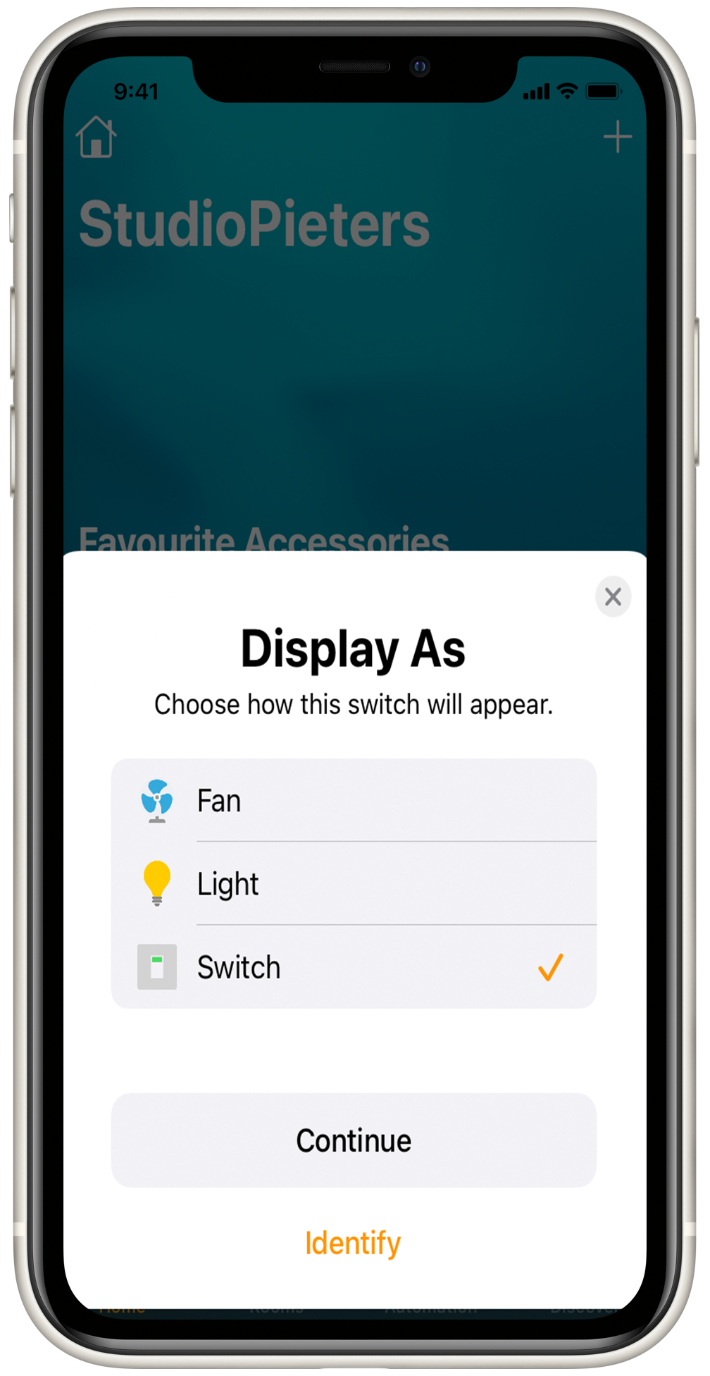
Display As: This setup has an extra option, display as, which enables you to add the switch function as a switch, a light, or a Fan. This enables you to use this code for more than only a switch, you can control any 230V device you connect to the relay.
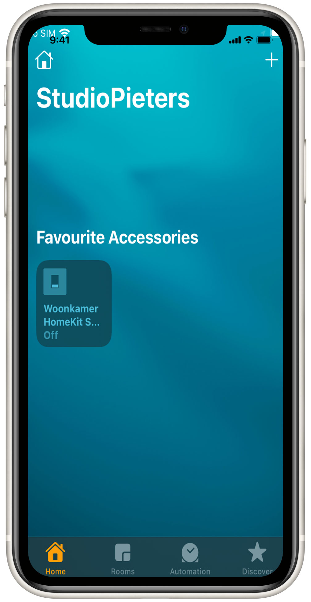
Explore Your HomeKit Switch Controls: Once successfully added, you will see the HomeKit switch button on your screen. You can now control the switch directly from the HomeKit app.
Dive Into Device Settings: Take a moment to explore the settings of your newly integrated device. You’ll find detailed information about its status and configuration.
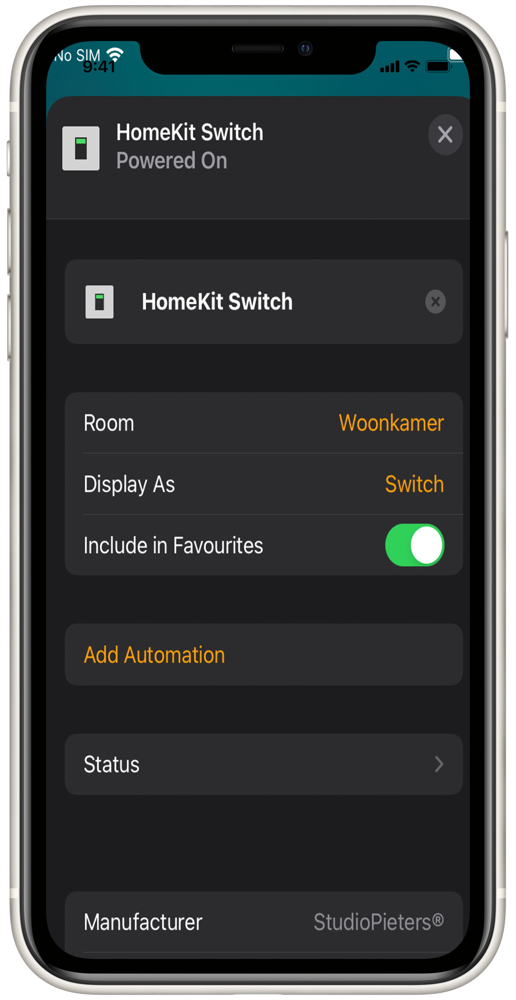
Customize Automations (Optional): If you desire more advanced functionality, consider adding automations to your HomeKit switch. This allows you to create custom routines tailored to your preferences.
With these steps completed, you’ve successfully connected your ESP32 device to HomeKit.

Conclusion
And so, fellow makers, join us as we dive into the world of smart home innovation with our ESP32-powered HomeKit switch. Whether you’re a DIY pro or just curious about creating a smarter home, there’s something here for everyone. So grab your tools, follow along, and get ready – because this is only the beginning of our HomeKit journey!